| Auxiliary Gauge Lighting for newer Module controlled Dash Lights |
| Introduction |
| |
| This How-To is for the lighting of newly installed gauges, and contolling them
with the same dashboard Dimmer circuit that the rest of the dash lights use. This How-To is for the
2003 Tahoe that uses a processor module to control the dash lighting, and other functions. (It probably
works on newer GM vehicles, as well.) The module in question is the Body Control Module (BCM).
The BCM is located under the steering wheel behind the Knee Bolster the flat dash panel below
the steering wheel. This How-To does not address the installation of the gauges, but only how
to illuminate the gauges after they are installed. |
| |
| Procedure |
| |
| The wires for the light bulb, regardless of the type LED or incandescent,
must be long enough to reach the Body Control Module under the dash. |
| |
 |
| Figure 1.Below the Dashboard |
| |
| Step 1. Remove the Dashboard Trim Ring. This is a matter of gently pulling
on the Trim Ring until the spring clips release it from the dashboard. |
| |
 |
| Figure 2. Dashboard Trim Piece |
| |
 |
| Figure 3. Back detail of the Dashboard Trim Piece showing the clips |
| |
| Step 2. Remove the drivers side fuse cover, and then the Knee Bolster from the bottom of the
dashboard. Remove the two 7mm bolts holding the bottom edge of the Knee Bolster near the parking brake release. NOTE: The
Trim Ring must be removed first in order to remove the Knee bolster as the Trim Ring holds the upper edge of the Knee Bolster. |
| |
| Step 3. Remove the four 10 mm nuts holding the Knee Bolster Reinforcement Plate. |
| |
| Step 4. Pull the C1 connector from the BCM. |
| |
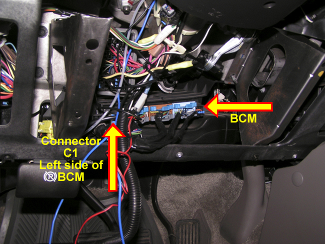 |
| Figure 4. Body Control Module beneath the Steering Wheel. |
| |
 |
| Figure 5. The C1 Connection Diagram. |
| |
| Step 5. Splice in the positive Light bulb lead to the Pin A red wire. Connect the
negative bulb to ground. Use one of the Knee Bolster Reinforcement Plate 10 mm nuts as the ground connection.
Test. |
| |
| Step 6. Clean up the excess wiring. Use wire ties as appropriate. |
| |
| Step 7. Replace the Knee Bolster Reinforcement Plate, and tighten the four 10 mm nuts
holding the Plate to the back of the dash. |
| |
| Step 8. Replace the Knee Bolster and secure it with the two 7 mm screws on the bottom
edge. Press the left side Fuse cover back into place. |
| |
| Step 9. Press the Dashboard Trim Ring back onto the Dashboard. |
| |
| Step 10. Done. |
| |
| To return to the How To Page, Click here. To
Get back to Big Red, Click here. |